How to print great B&W photos (2) - redirecting the CMY channels
Ink channel definitions relevant to R2880 need to be modified so that in three colour composite mode the cyan, magenta, and yellow inks are substituted with the LLK, PK, and LK inks.
This article is part two of a series. The first part can be found here. It describes the general approach and gives the link to PhotoGP.
Pure Composite mode set up in PhotoGP
Once the R2880 printer is set up and the PhotoGP plugin is installed correctly for Adobe Photoshop CS4, we proceed to redirect some of the ink channels by modifying the corresponding xml file in the photoGP directory. With the Gutenprint driver that forms the core of PhotoGP, we can get the R2880 to print in "pure composite mode" by using only the cyan (C), magenta (M), and yellow (Y) channels. If our black and white image is presented to the gutenprint driver in RGB mode without converting it into grayscale in Photoshop, each shade of gray will be made up from three equal but independent colour channels values. So for a gray level of 50%, the (r,g,b) values would be (128,128,128) assuming eight bits per colour channel. For white the (r,g,b) values would be (255,255,255) and the CMY values, being their inverse, would be (0,0,0) which means that no ink is deposited from any channel. By the way, Gutenprint drivers use 16 bits per channel when printing, so it is best to use 48 bit images (16 bits per channel) to get maximum tonal smoothness. We will redirect each of the C, M, and Y channels, containing identical values, to the three black and white inks in the PK (or MK if you are using matte paper), LK, and LLK positions. The mapping I followed is this:
C -> LLK, M -> PK, and Y -> LK.
Each channel value now needs to be modified with an ink density shaping function. This way the LLK ink is used only over the white to light gray tones, and will be turned off when the gray value goes higher than a certain density. Care is taken to smoothly switch from one ink to the other and to blend two or more inks as necessary to achieve the final tonal range and bias (cool, warm, or neutral). Before this however, we make our life a bit easier by figuring out the per channel density and tonal value as a function of the input. For any given channel value, the K ink would print the darkest and the LLK ink the lightest (remember, the channel values are identical for a given shade of gray). The density values can be determined by printing out a CMY test strip and using a spectrophotometer like the ColorMunki and the program ArgyllCMS. This is the method I followed. I do not give the details here since ArgyllCMS is well documented, but I describe below how to redirect the ink channels.
Changing the channels
The printer model number for the R2880 is 98 as can be seen by checking the printers.xml file in the xml directory of PhotoGP. The corresponding model parameters are kept in PhotoGP/xml/escp2 directory in the file model_98.xml:
<escp2:model id="98">
<media src="escp2/media/f360_ultrachrome_k3v.xml"/>
<inputSlots src="escp2/inputslots/r2880.xml"/>
<qualityPresets src="escp2/qualitypresets/v2880.xml"/>
<inkGroup src="escp2/inks/f360_ultrachrome_k3v.xml"/>
<mediaSizes src="escp2/mediasizes/standard.xml"/>
The three colour composite slot will be used to map the black inks. So in the inkgroup file escp2/inks/f360_ultrachrome_k3v.xml, make the following changes (highlighted with bold characters):
<InkName translate="text" name="CMY" text="Three Color Composite" InkID="CMYK">
<Channels>
<channel name="standard_cyan" index="1">
<HueCurveParam name="CyanHueCurve"/>
<subchannel color="0" subchannel="3" headOffset="1" name="Cyan" text="Cyan" translate="text">
<ChannelDensityParam name="CyanDensity"/>
</subchannel>
</channel>
<channel name="f360_standard_magenta" index="2">
<HueCurveParam name="MagentaHueCurve"/>
<subchannel color="0" subchannel="0" headOffset="1" name="Magenta" text="Magenta" translate="text">
<ChannelDensityParam name="MagentaDensity"/>
</subchannel>
</channel>
<channel name="standard_yellow" index="3">
<HueCurveParam name="YellowHueCurve"/>
<subchannel color="0" subchannel="1" name="Yellow" text="Yellow" translate="text">
<ChannelDensityParam name="YellowDensity"/>
</subchannel>
</channel>
</Channels>
Cyan now points to slot LLK, Yellow to slot LK, and Magenta to slot MK/PK. This change means that when you use PhotoGP plugin to do printing with Photoshop, the CMY composite mode will print only in black and white and not in the original CMY mode.
Ink density test strips for curve generation
Now the CMY channel curves need to be set up. A 16 bit/channel 360 pixels/inch CMY file without any embedded profile is given below.
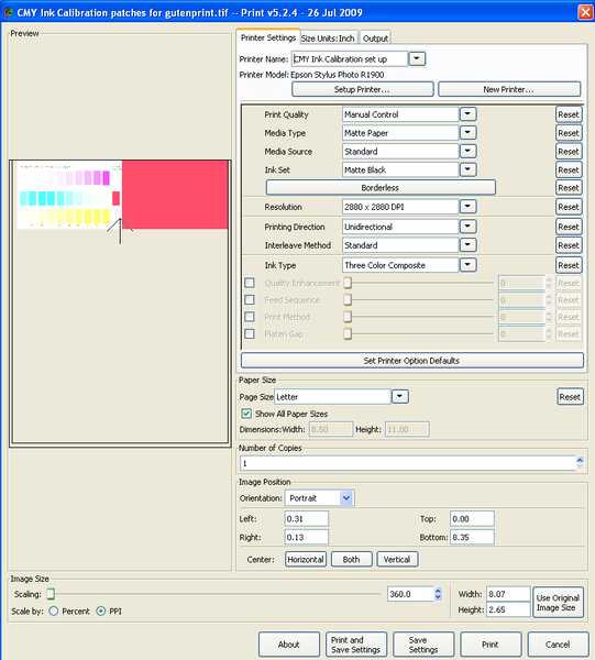
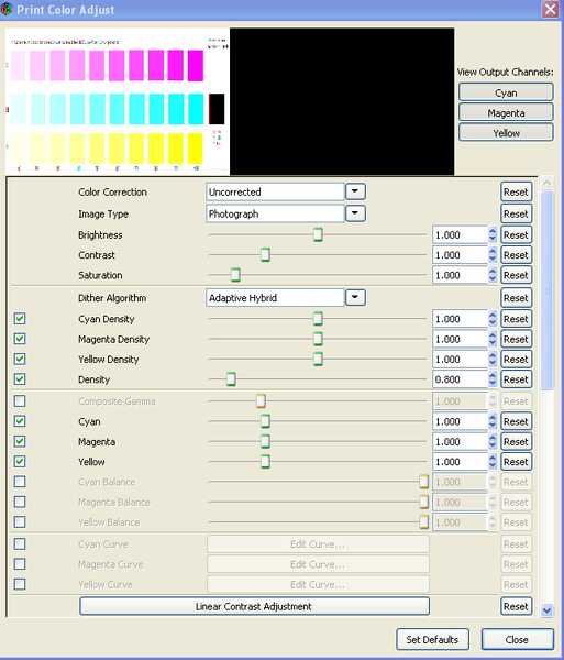
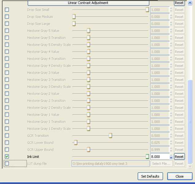
Open this file in Photoshop, making sure to leave it uncorrected if Photoshop suggests applying a profile to the file. Export it into PhotoGP and set up a printer with the suggested settings shown in the images below of the PhotoGP set up screen. Print the image and let it dry for a few hours. The patches will be in shades of gray if you followed the instructions above without mistakes. Their L*a*b* values can now be measured using a spectrophotometer as indicated earlier.


In the next part of the article, we shall look at an example printout to assess the uncalibrated gray scale output of the printer and discuss how to use that data to linearize the printer response.
